Elementor #1101
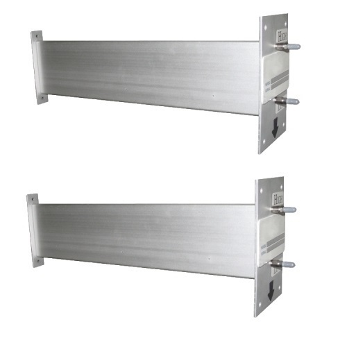
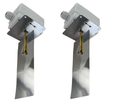
| Duct Air Flow Measuring Probe | |
|---|---|
Rs 10,500 / Piece | |
| Brand | Dwyer Usa |
| Accuracy | +/-2% |
| Flow range | 400 fpm (2.03 m/s). TO 12000 fpm (60.96 m/s). |
| Condition | New |
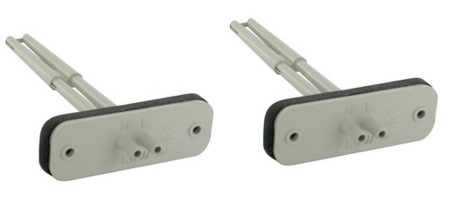
Rectangular Duct Probe Installation:
Circular Duct Models:
Sometimes field calibration may be required if the probe is installed in a bad location i.e. immediately downstream of an elbow. In order to calibrate, you must either perform a traverse of the duct or a sum of the air registers and compare this with the DAFM output. Then, you must make the correction to the effective area in the computer to make up for the error.
Upon final installation, the device should be checked once a year for a build up of dirt or debris that can be common in an HVAC system. Also check the mounting stability once a year. Other than this no routine maintenance is required. The DAFM model is not field serviceable and should be returned if repair is needed (field repair should not be attempted and may void warranty). Be sure to include a brief description of the problem plus any relevant application notes. Contact customer service to receive a return goods authorization number. | |
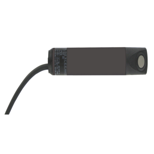
| Air Flow Switch | |
|---|---|
Rs 2,950 / Piece | |
| Brand | Dwyer Usa |
| Warranty | YAS |
| Condition | New |
Air Flow Switch | |
| Air Velocity Transmitter | |
|---|---|
Rs 38,500 / Piece | |
| Brand | Dwyer Usa |
| Condition | New |
Air Velocity Transmitter | |
| Averaging Flow Sensor | |||||||||||||||||||||||
|---|---|---|---|---|---|---|---|---|---|---|---|---|---|---|---|---|---|---|---|---|---|---|---|
Rs 2,500 / Piece | |||||||||||||||||||||||
| Brand | Dwyer Usa | ||||||||||||||||||||||
Averaging Flow Sensor Technical Specification:
| |||||||||||||||||||||||
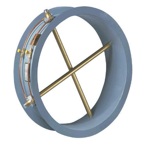
| Duct Mounted Airflow Measurement Station | |
|---|---|
Rs 17,500/ Piece | |
| Accuracy | 2% |
| Condition | New |
Duct Mounted Airflow Measurement Station
Application:
FLST Specification Guide:
| |
| Fume Hood Monitor | |
|---|---|
Rs 9,500 / Piece | |
| Brand | DWYER USA |
Fume Hood Monitor
| |
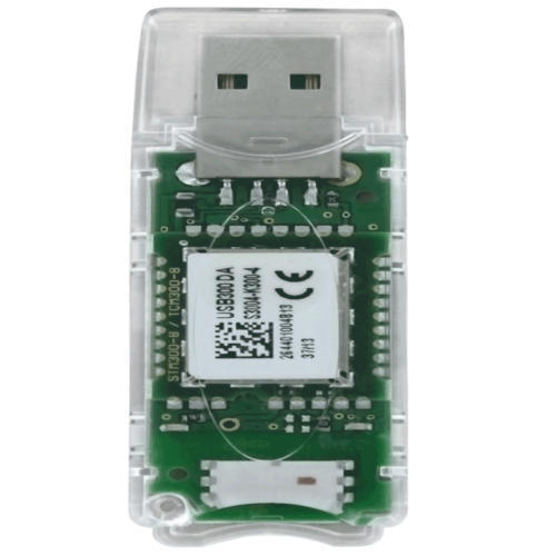
| USB Wireless Receiver | |||||||
|---|---|---|---|---|---|---|---|
Rs 900 / Piece | |||||||
| Model Number | DWYER USA % | ||||||
| Condition | New | ||||||
USB Wireless Receiver
Applications:
Other Details:
| |||||||
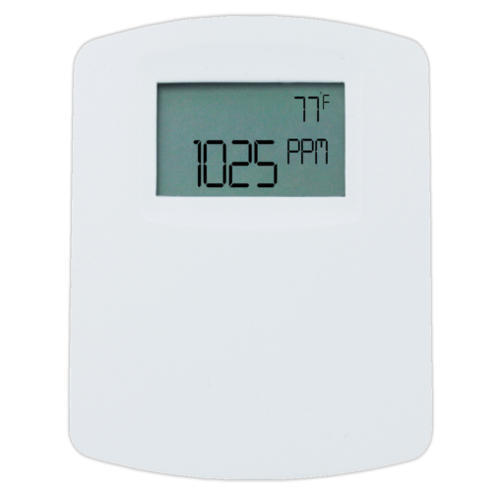
| Temperature Transmitter | |||||||||||||||||
|---|---|---|---|---|---|---|---|---|---|---|---|---|---|---|---|---|---|
Rs 8,500 / Piece | |||||||||||||||||
| Brand | DWYER USA % | ||||||||||||||||
| Condition | New | ||||||||||||||||
Carbon Dioxide and Temperature Transmitter
Technical Specification:
| |||||||||||||||||
| Communicating Carbon Dioxide Detector | |
|---|---|
Rs 37,500 / Piece | |
| Model | DWYER USA % |
| Display Type | Digital |
Communicating Carbon Dioxide Detector | |
| Carbon Dioxide Temperature Transmitter | |
|---|---|
Rs 8,500 / Piece | |
| Brand | DWYER USA |
Carbon Dioxide Temperature Transmitter
| |
| Carbon Monoxide Transmitter | |||||||
|---|---|---|---|---|---|---|---|
Rs 7,000 / Piece | |||||||
| Model Number | DWYER USA % | ||||||
| Measurement Range | 0 to 200 ppm. | ||||||
| Accuracy | +/-2% FS at the time of calibration. | ||||||
Carbon Monoxide Transmitter
| |||||||
| Carbon Monoxide and Nitrogen Dioxide Gas Transmitter | |||||||||||||||||||||||
|---|---|---|---|---|---|---|---|---|---|---|---|---|---|---|---|---|---|---|---|---|---|---|---|
Rs 20,000/ Piece | |||||||||||||||||||||||
| Brand | DWYER USA | ||||||||||||||||||||||
Carbon Monoxide and Nitrogen Dioxide Gas Transmitter
Technical Specification:
| |||||||||||||||||||||||
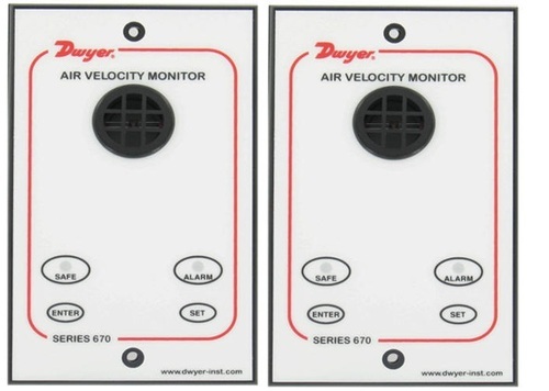
| Fume Hood Monitor | |
|---|---|
Rs 9,500 / Piece | |
| Brand | DWYER USA |
Fume Hood Monitor
| |
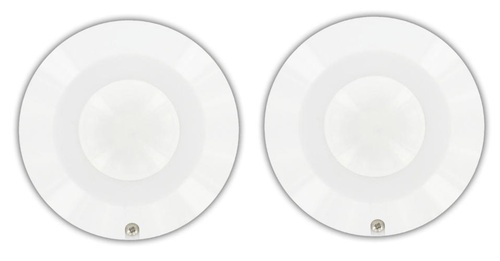
| Occupancy Sensor | |
|---|---|
Rs 3,500 / Piece | |
| Brand | DWYER USA |
Occupancy Sensor
Wiring: | |
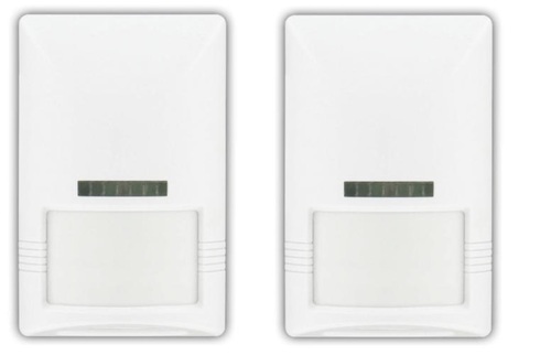
| Wall Mount Occupancy Sensor | |
|---|---|
Rs 9,500 / Piece | |
| Range | 49.2 ft (15 m). |
| Weight G | 3.2 oz (90.7 g). |
| Brand | DWYER USA |
Wall Mount Occupancy Sensor
| |