Differential Pressure Gauge Wholesaler Dealers, Dwyer Distributor Envirotech Industrial India, Dwyer Distributors India, Dwyer Fittings Accessories, Dwyer Instruments, Dwyer Instruments Distributors Delhi, Dwyer Instruments Distributors in Delhi, Dwyer Instruments Distributors in India, Dwyer Instruments Distributors Wholesaler In India, Dwyer Magnehelic Gauge Wholesale Suppliers India, Dwyer Pressure Gauge Wholesaler In INDIA, Dwyer Products INDIA DELHI, Dwyer Usa Magnehelic Gauge Wholesale Noida
Control The Critical With The > Series 2000 Magnehelic Differential Pressure Gauge
Control The Critical With The > Series 2000 Magnehelic Differential Pressure Gauge
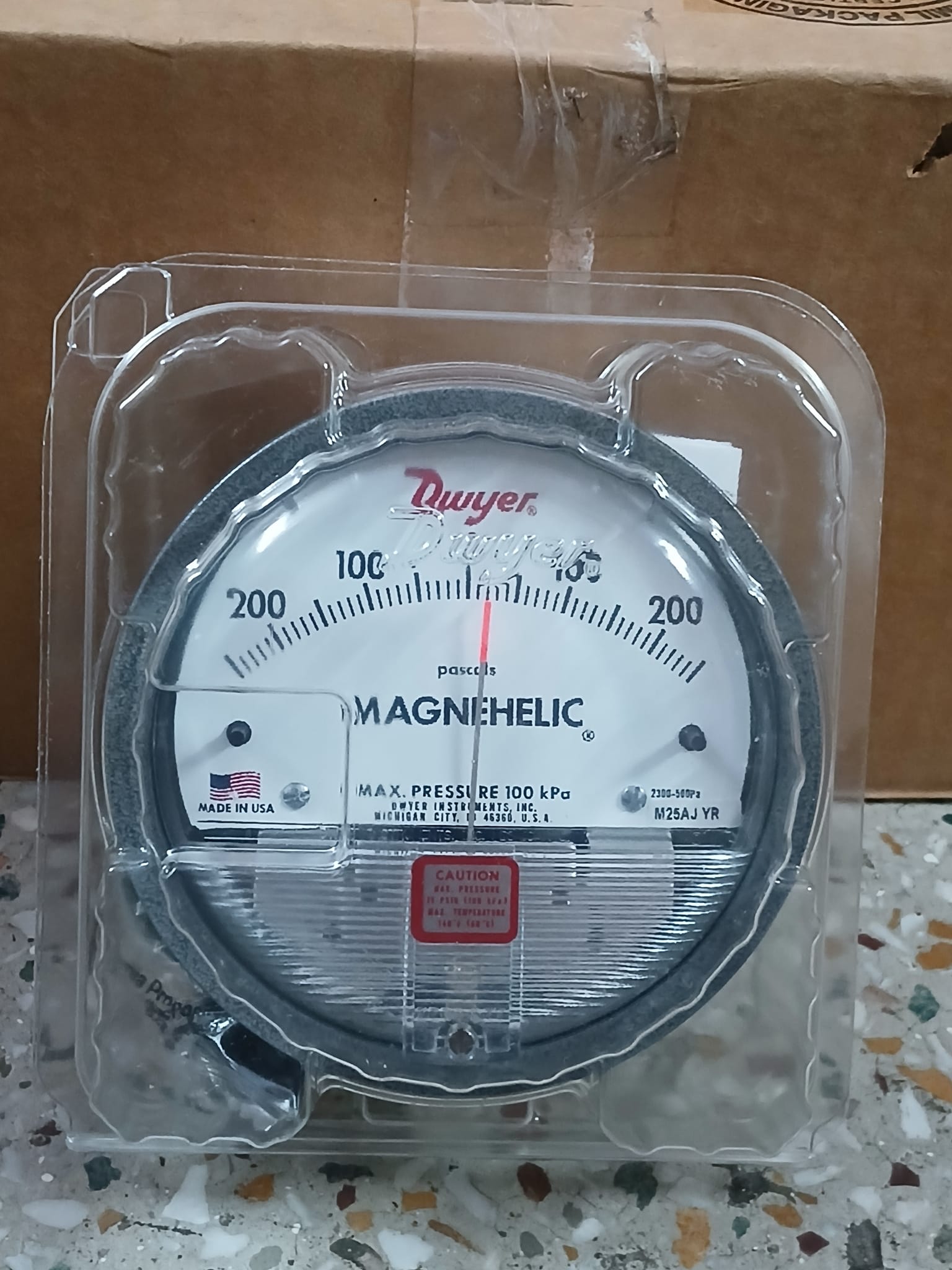
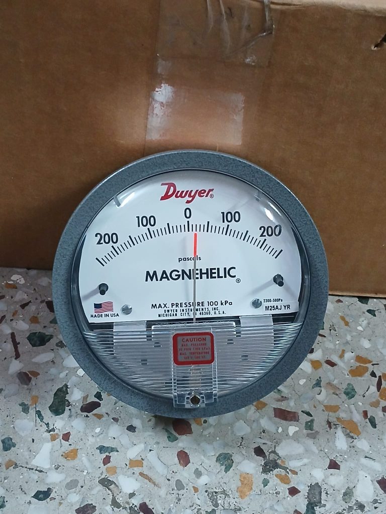
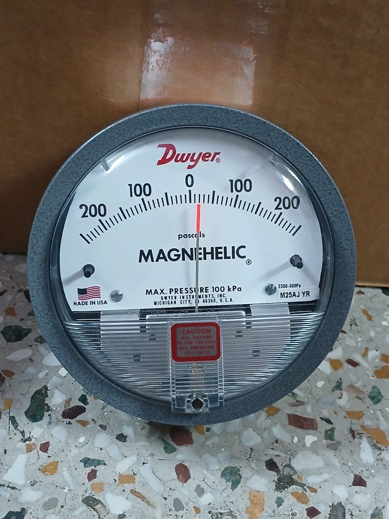
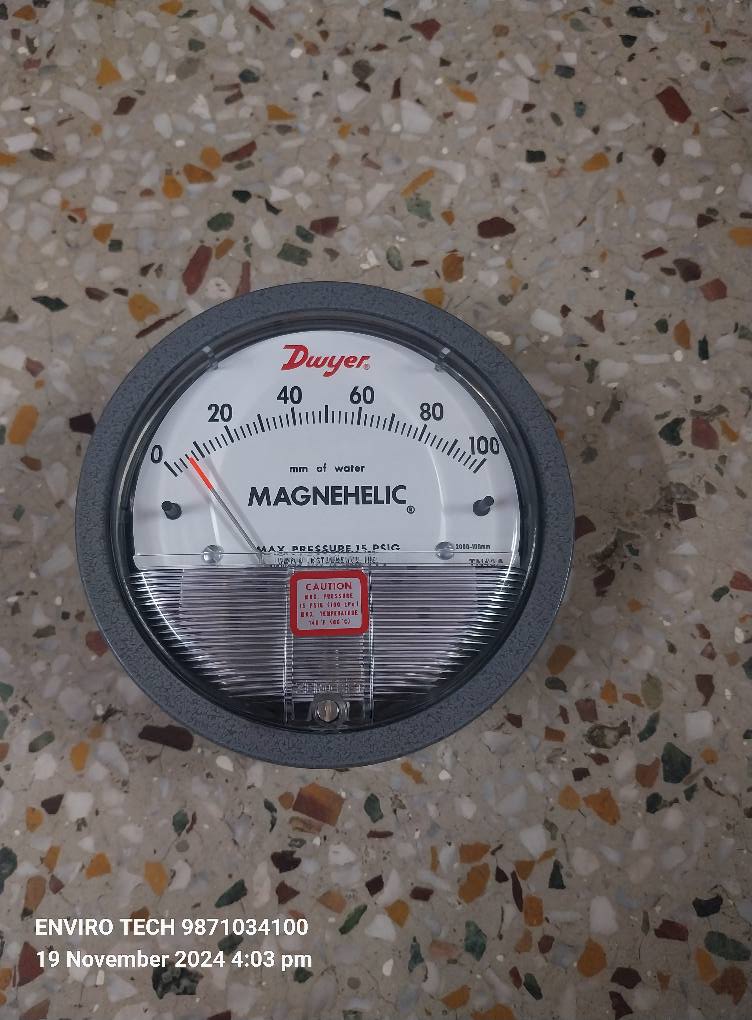
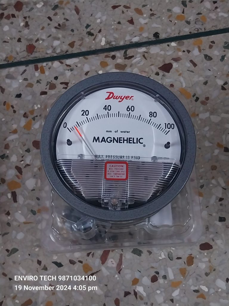
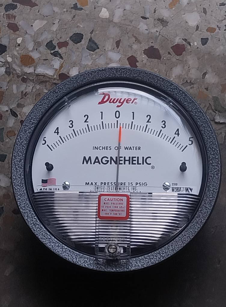
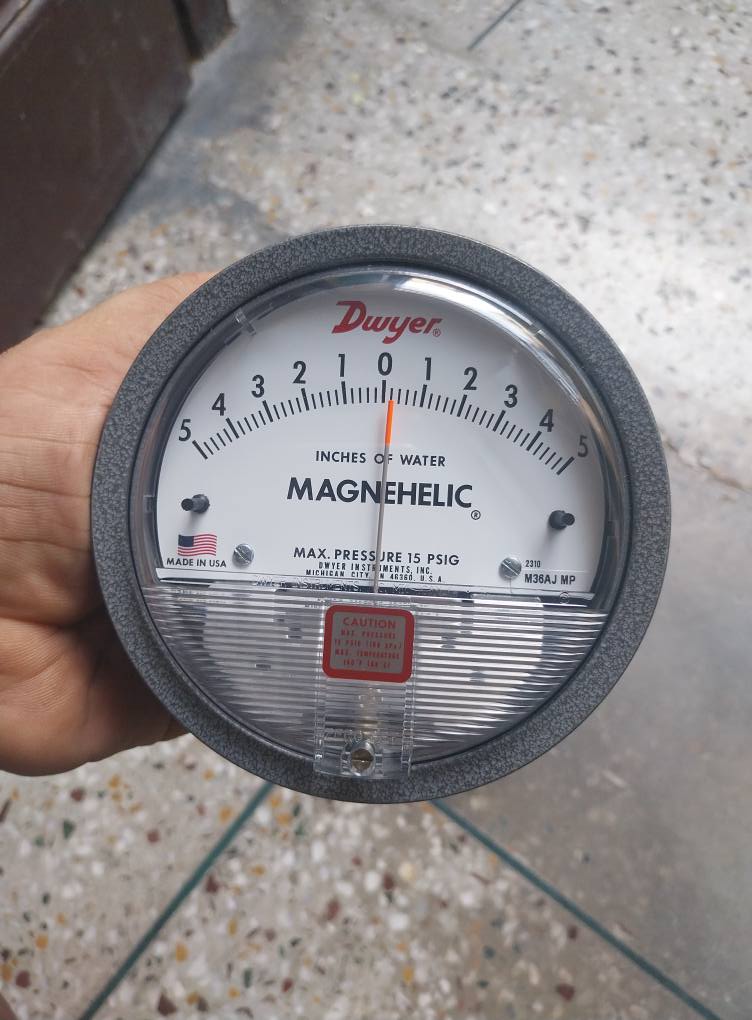
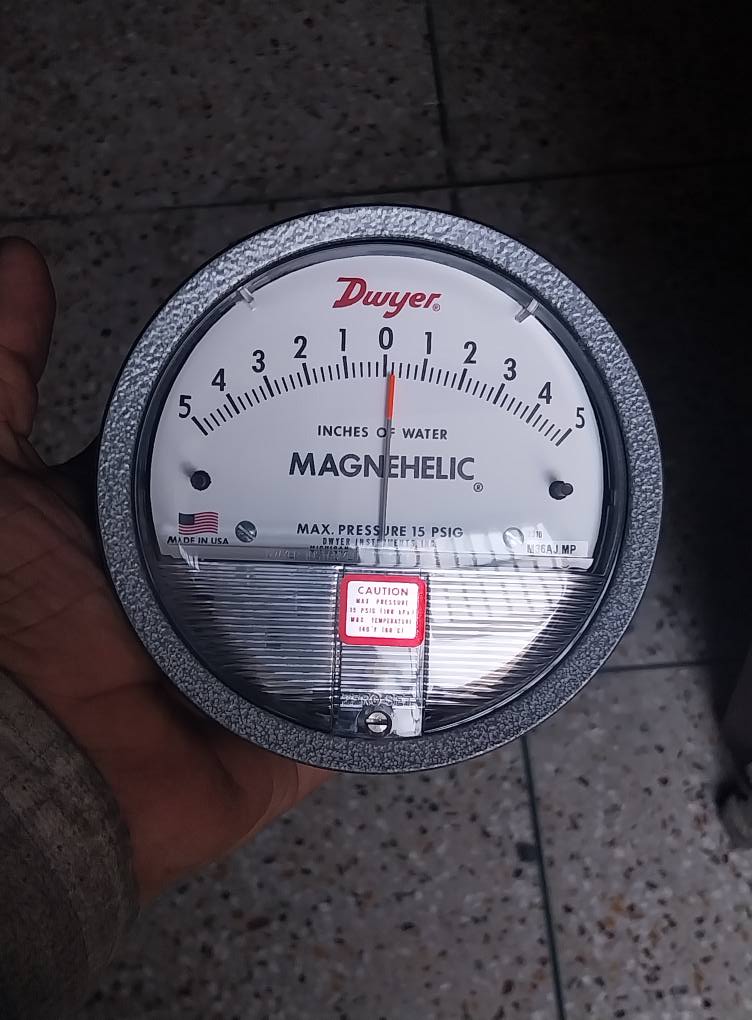
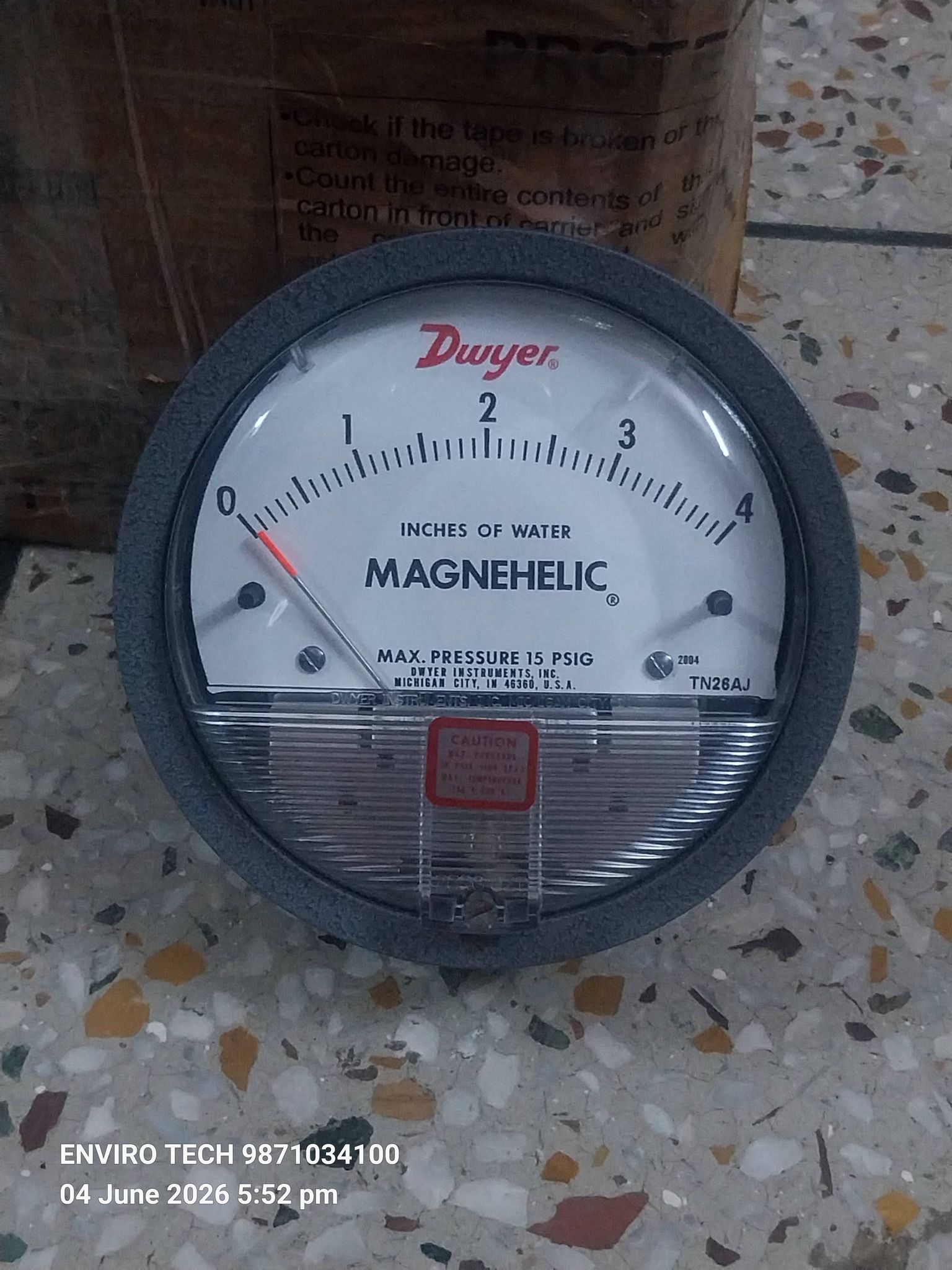
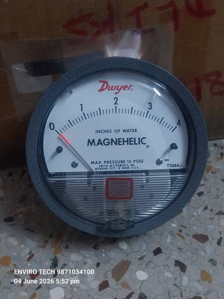
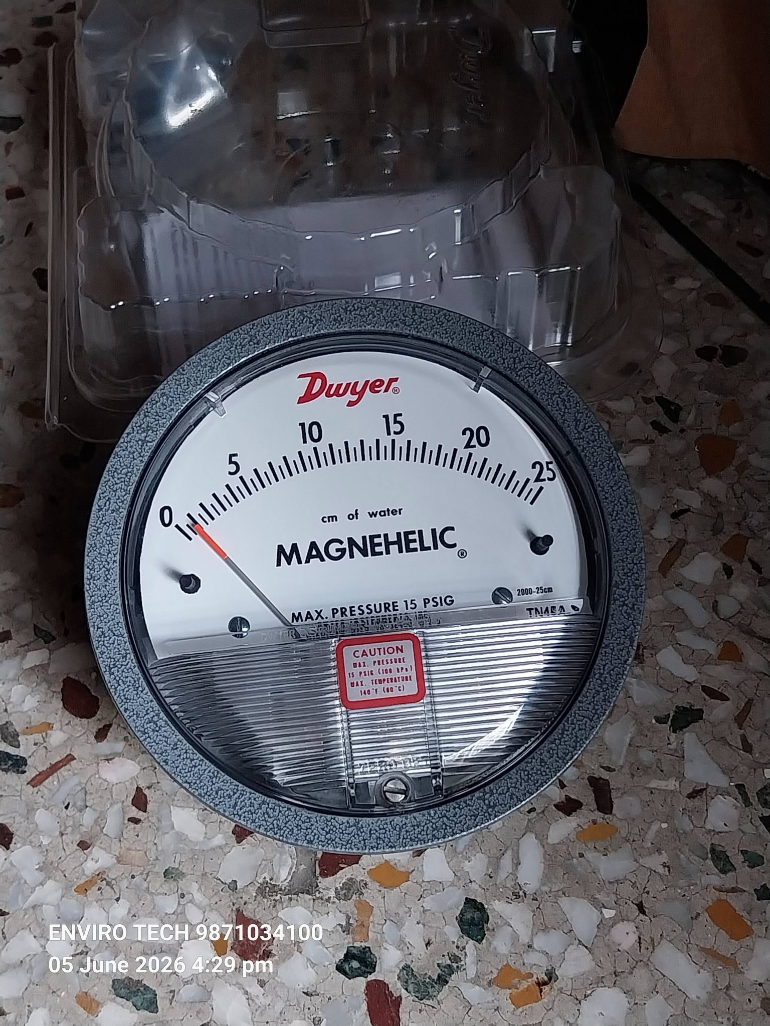
The Dwyer Instruments Series 2000 Magnehelic® Differential Pressure Gauge is The Industry Standard For Monitoring Low Differential Pressure, Providing Rapid, Accurate, And Reliable Measurements of Air And Non-Combustible Gases. Engineered to “Control The Critical,” This Gage is Essential For Applications Requiring Precise Environmental Control, Such as Clean Rooms, Medical, And HVAC Systems.
Key Features and Benefits
- Rapid Response: Patented Design Quickly Indicates Pressure Changes, Ensuring No Delay in Assessing Critical Situations.
- High Accuracy: Standard accuracy is 2% of full scale, with High-Accuracy Models (-HA) Available at 1%.
- Durable & Robust: The Die-Cast Aluminum Housing and Acrylic Cover are Built to Last, with IP67 Weatherproofing.
- No Power Needed: Operates mechanically using a diaphragm And Magnet, Requiring Zero Electricity.
- Easy-to-Read: Features a 4-inch Dial That Allows For Viewing From a Distance.
- Frictionless Movement: Prevents Wear and Provides Long Service Life, Reducing Maintenance Downtime.
- Versatile Mounting: Can Be Flush Or Surface Mounted, With Options For Pipe Mounting.
Primary Applications
The Series 2000 is Used to Measure Positive, Negative, or Differential Pressures in a Variety of Industries:
- Filter Monitoring: Indication of Pressure Drop Across Air or Gas Filters in AHUs.
- Room Pressurization: Monitoring Air Pressure in Clean Rooms, Laboratories, And Hospitals.
- HVAC Systems: Monitoring Fan Pressure, Blower Vacuum, And Air Velocity.
- Process Automation: Checking Gas-Air Ratio Controls And Automatic Valves.
Specifications & Customization
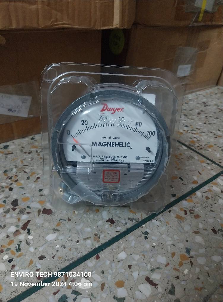
- Pressure Ranges: Wide Variety of Models Available, Including 0-60 Pa, 0-25 mm H2O, and 0-0.5″ w.c..
- Pressure Limits: Up to 35 psi (2.41 bar) for Standard Models.
- Overpressure Protection: Features a Blow-Out Plug That Releases Internal Pressure at Roughly 25 PSIG.
- Options: Available With Optional Stainless Steel Bezel, Higher Pressure Ranges, or High-Accuracy Models.
Additional Information:
- Item Code: Control The Critical With The > Series 2000 Magnehelic Differential Pressure Gauge
- WhatsApp No.9871034100,9868958924,9650264867,9716640145,8368866030,8368801023
- www.envirotechindustrialproducts.net
- www.envirotechindustrialproduct.net
- www.envirotechindustrialproductsindia.in
- www.envirotechindustrialproductsdelhi.com
- www.envirotechindustrialproduct.info
- www.envirotechindustrialproducts.info
- www.envirotechdelhi.com


Magnehelic < Differential Pressure Gauges < Accuracy: 3%
Magnehelic < Differential Pressure Gauges < Accuracy: 3%
SERIES 2000 MAGNEHELIC® DIFFERENTIAL PRESSURE GAGES Indicate Positive,Negative or Differential,Accurate within 1%
Select the Series 2000 Magnehelic® Gage for a versatile low Differential Pressure Gage With a Wide Choice of 81 Models and 27 Options To Choose From. Using Dwyer’s Simple,frictionless Magnehelic® Gage movement, it quickly indicates air or noncorrosive gas pressures–either positive,negative vacuum or differential.The design resists shock,vibration,over-pressures and is weatherproof to IP67. Select the -HA High Accuracy Magnehelic® Gage option for an accuracy within 1% of full scale, located below in the Product Configurator. Also included with the –HA option at no extra cost are a mirrored scale overlay and a 6 point calibration certificate.
NIST CALIBRATION available in Product Configurator.
Note: May be used with Hydrogen. Order a Buna-N diaphragm. Pressures must be less than 35 psi.
Please see Series AT-2000 for ATEX approved.
California Residents: Click Here for Proposition 65 WARNING.
PRODUCT APPLICATIONS
Additional Information: