+(91)-9871034100
PHONE NO
07AOSPS8386M1ZM
GST NO

Elementor #1101

Duct Air Flow Measuring Probe

Rs 10,500 / Piece

BrandDwyer Usa
Accuracy+/-2%
Flow range400 fpm (2.03 m/s). TO 12000 fpm (60.96 m/s).
ConditionNew


Duct Air Flow Measuring Probe

The DAFM Model Duct Air Flow Measuring Probe :
Uses evenly distributed total and static pressure measuring points to deliver an accurate measurement of flows in a duct. The Air Flow Measuring Probe can be completely installed from outside of the duct making it very easy to install. With its lightweight and durable construction in addition to its ease of installation, this product lends itself to being used in the HVAC industry. These air flow measuring probes may be ordered to fit into either round or rectangular duct installations.

Installation:
When you unpack the Model DAFM Duct Air Flow Measurement Probe ensure that there is no visible damage from shipping. Inspect each sensing point on the probes to ensure that they are not filled with debris from shipping. If there is obvious shipping damage, the probe must be replaced prior to use in order to avoid inaccurate measurements. Please contact Dwyer Instruments, Inc. if it is necessary to replace your air flow measurement probe.

Rectangular Duct Models:
Determining Probe Number and Placement for Rectangular Ducts

  • To determine the number of probes you need please consult the chart below.
  • In order to determine where to place your probes, divide the short duct dimension by number of probes.
  • Divide the result by two and this will be the distance from the side of the duct to the first probe location.
  • The next probe will be placed two times the resulting distance from step two from the first probe. So, if the first probe was placed 4 ̋ from the side of the duct, your next probe would be placed 8” from the first probe, or 12 ̋ from the side of the duct.
  • Continue this pattern until you have determined all probe locations.


Rectangular Duct Probe Installation:

  • Cut 4 ̋ X 1 ̋ holes at locations calculated above in side of duct.
  • Place silicon bead around holes.
  • Slide DAFM into holes and screw four self drilling screws into duct to attach DAFM.
  • Connect 1/4 ̋ OD plastic tubing to barb fittings on DAFM.
  • Check all fittings and tubing connections for leaks using a leak detector.
  • Tee all high and low ports into one high and one low line and connect to transmitter or gage.
  • The devices should be checked once a year for build-up of dirt of debris common in an HVAC system.

Circular Duct Models:

  • Determining Probe Number and Location for Round Ducts Note that in round ducts only two probes are needed. The quantity of probes needed does not depend on size of the duct.
  • Locate probes 90 degrees apart. See Figure 2 for an example.


Calibration:

Sometimes field calibration may be required if the probe is installed in a bad location i.e. immediately downstream of an elbow. In order to calibrate, you must either perform a traverse of the duct or a sum of the air registers and compare this with the DAFM output. Then, you must make the correction to the effective area in the computer to make up for the error.


Maintenance:

Upon final installation, the device should be checked once a year for a build up of dirt or debris that can be common in an HVAC system. Also check the mounting stability once a year. Other than this no routine maintenance is required. The DAFM model is not field serviceable and should be returned if repair is needed (field repair should not be attempted and may void warranty). Be sure to include a brief description of the problem plus any relevant application notes. Contact customer service to receive a return goods authorization number.

Air Flow Switch

Rs 2,950 / Piece

BrandDwyer Usa
WarrantyYAS
ConditionNew

Air Flow Switch

The SERIES AVFS Adjustable Air Flow Switch is specifically designed to monitor air flow in ducts and provides a 3 A contact output to indicate a change or loss of flow. The AVFS provides a ±5% set-point repeatability across a full scale range of 1-10 m/s (197-1969 fpm) and includes a mounting bracket for quick duct mounting.
Application:Fan monitoring Filter monitoring Damper feedback Air handler 
The new Series AVFS Adjustable Air Flow Switch complements  the  Dwyer Instruments line of thermo-anemometer transmitters and handheld instruments. The AVFS is specifically designed to monitor air flow in ducts and provides a 3A contact output to indicate a change or loss of flow. Simply turn on the fan or air handling unit and adjust the set-point via the potentiometer to show normal status. Then alter a damper or decrease fan speed to activate the AVFS. The AVFS will signal a loss of flow and the N.O. SPST output will indicate the detected decrease. For ease of installation and system trouble-shooting, the Series AVFS possesses a red/green LED indication to provide local status if the air flow is above (green) or below (red) the set-point.  The AVFS Series Adjustable Air Flow Switches come in a compact, rugged PBT enclosure that is rated NEMA 4X (IP65), making them ideal for any ventilation system installation or similar BAS application. 
Mounting:Mount the airflow monitor by means of the mounting clamp provided. Diameter of the mounting hole for the unit: .9 in (24 mm) mm. If mounting is to be airtight, use the gasket provided. The sensing head must be completely immersed into the airflow and should be in the range of the highest flow velocity, if possible. 
Maintenance:Upon final installation of the Series AVFS Air Flow Switch, no routine maintenance is required. The Series AVFS is not field serviceable and should be returned if repair is needed (field repair should not be attempted and may void warranty). Be sure to include a brief description of the problem plus any relevant application notes. Contact customer service to receive a return goods authorization number before shipping.

Air Velocity Transmitter

Rs 38,500 / Piece

BrandDwyer Usa
ConditionNew

Air Velocity Transmitter

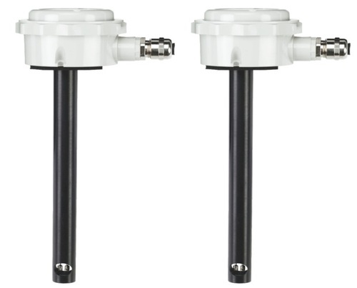
The SERIS AVU Air Velocity Transmitter is ideal for a wide range of HVAC measurement and control applications, particularly in complete building control and energy management systems. The Series AVU Transmitter operates by measuring the heat loss from one of the two sensing elements in the air stream, then calculating the air velocity. Units are virtually immune to drift due to the design of the sensing element, which makes the transmitter accurate over the whole air velocity range.
The  Series  AVU  Air  Velocity  Transmitters from  Dwyer Instruments  are  suitable  for  measuring  air  velocity  within  a  duct and giving 4-20 mA or 0-10 V linear outputs. A typical application would be in a VAV air conditioning system. 
The transmitters operate by measuring the heat loss from one of two sensing elements in the airstream and hence calculating the air velocity. The special design of these elements makes the transmitter accurate over the whole air velocity range and gives excellent immunity to drift. 
The sensing elements are clad in metal ensuring a long service life and enabling the sensors to be cleaned easily. 
Installation:Electromagnetic CompatibilitySeries AVU Air Velocity Transmitters have built in immunity to electrical interference. However, to achieve full immunity meeting the standards described below, a screened cable must be used correctly. The cable screen must be earthed at the enclosure of the controller/power  supply  and  connected  to  the  screen  inside  the AVU casing using the procedure described on the back page. The inside of the transmitter and the sensing elements near the end ofthe probe must be protected from electrostatic discharge at all times.

Averaging Flow Sensor

Rs 2,500 / Piece

BrandDwyer Usa

Averaging Flow Sensor

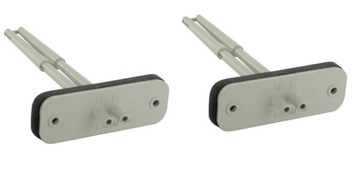
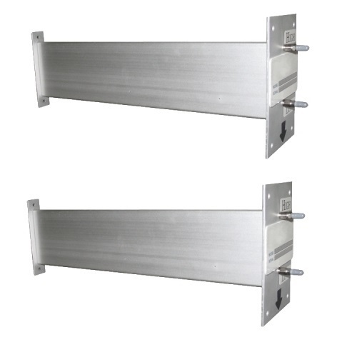
The  Series  SSS-1000  Lightweight  Averaging  Flow Sensor From  Dwyer  Instruments,  Inc.  is  ideal  for  sensing differential pressure in the inlet section of variable air volume terminal units and fan terminal units. They can also be used to sense differential pressure at other locations in the main,or branch duct systems.
The Series SSS-1000 Lightweight Flow Sensor is ideal for sensing differential pressure in the inlet section of variable air volume terminal units and fan terminal units. Units can also be used to sense differential pressure at other locations in the main or branch duct systems.
The “H” port senses total pressure and the “L” port senses static pressure. The difference between these signals is the differential, or velocity pressure.Models  offer  up  to  four  sensing  points  and  lengths  of  3- 5/32 ̋ to 9-29/32 ̋ (8.02 to 25.26 cm) to accommodate box size diameters of 4 ̋  to 16 ̋ (10.16 to 40.64 cm)
Installation:The Series SSS-1000 utilizes 1/4 ̋ I.D. tubing for 3/8 ̋ O.D. tubing. First check that there are no sharp bends in the tubing  at  any  connection.  Bends  and  creases  may  leak  over time as the tubing ages. Connect  the  “H”  Port    to  the  high  input  on  the  differential pressure gage, transmitter, or switch.Connect  the  “L”  Port  to  the  low  input  on  the  differential pressure gage, transmitter, or switch.
Mounting:Install  the  unit  horizontally  to  assure  accurate  velocity readings.Determine the duct’s flow direction and install the Series SSS-1000 based on the unit’s flow arrow imprint.Cut a 7/8 ̋ hole in the ducting to accept the unit.Attach using two self-tapping screws inserted in the 3/16 ̋ mounting holes.
Maintenance:Sensing orifices must be kept free of dust accumulation or debris.The Series SSS-1000 Lightweight Averaging Flow Sensors are not field repairable. If you wish to return a unit contact customer  service  to  receive  a  return  goods  authorization number before shipping.

Technical Specification:

ModelLength (Dimension A)
SSS-10023-5/32 ̋ (8.02 cm)
SSS-10035-13/32 ̋ (13.73 cm)
SSS-10047-21/32 ̋ (19.55 cm)
SSS-10059-29/32 ̋ (25.26 cm)
SSS-100612-1/2 ̋ (31.75 cm)
SSS-100714-3/4 ̋ (37.47 cm)
SSS-100817-1/8 ̋ (43.50 cm)
SSS-100919-13/32 ̋ (49.29 cm)
SSS-101021-21/32 ̋ (55.01 cm)
SSS-101123-29/32 ̋ (60.72 cm)

Duct Mounted Airflow Measurement Station

Rs 17,500/ Piece

Accuracy2%
ConditionNew

Duct Mounted Airflow Measurement Station

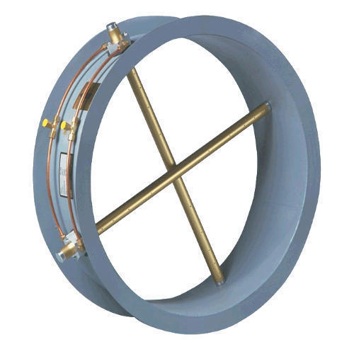
The SERIES FLST Airflow Measurement Station is easy to install — simply connect the tubing to the station fittings, then to a differential pressure manometer, gage, transmitter or switch. Single or multiple airflow elements are factory mounted and pre-piped in a casing designed for flanged connection to the duct work. Standard materials consist of a G90 galvanized casing and 6063-T5 anodized aluminum flow sensors, suitable for most HVAC applications.

The Series FLST utilizes an airflow averaging element in a head-type device, generating a differential (velocity) pressure signal similar to the orifice, venturi, and other had producing primary elements. Strategically located sensing ports continually sample the total and static pressures when inserted normal to flow.

Total pressure sensed by the upstream ports are continually averaged within the airflow element in an isolated chamber. The static sensing ports are averaged in a second isolation chamber. Multiple elements are joined together for connection to a differential measurement device (gage, transmitter, etc.) for flow measurement and indication purposes.

Features: 

  • Low signal-to-noise ratio
  • Factory mounted and pre-piped in a flanged duct section (casing)
  • Standard construction includes galvanized casing and 6063-T5 anodized aluminum flow sensors
  • Standard airflow stations can be operated (in air) continuously in temperatures up to 350°F or intermittently in temperatures up to 400°F


Options:

  • IM – Internal Pressure Connections.
  • F – (Oval Stations Only).

Application:

  • Building air intake and exhaust flow rate measurement
  • HVAC air flow measurement


FLST Specification Guide:

  • Provide where indicated and/or scheduled airflow traverse elements capable of continuously monitoring the fan or duct air volumes they serve.
  • Each element shall be designed and built to comply with, and provide results in accordance with, accepted practice for duct system traversing as
  • defined in the ASHRAE Handbook of Fundamentals, AMCA publication 203, as well as the Industrial Ventilation Handbook. The number of sens-
  • ing ports on each element, and the quantity of elements utilized at each installation, shall comply with ASHRAE Standard #111 for equal area duct
  • traversing.
  • Each airflow measuring element shall contain multiple total and static pressure sensing ports placed along the leading edge of the cylinder. The static pressure chamber shall incorporate dual offset static taps on opposing sides of the averaging chamber, so as to be insensitive to flow angle variations of as much as ±20 degrees in the approaching airstream.
  • The airflow traverse elements shall be capable of producing steady, non-pulsating signals of true total and static pressure, with an accuracy of 2% of actual flow for operating velocities as low as 100 feet per minute (fpm). Signal amplifying sensors requiring flow correction (K factors) for field calibration are not acceptable.
  • The airflow traverse elements shall not induce a measurable pressure drop, greater than 0.18 inch at 4,000 fpm. The units sound level within the duct shall not be amplified, nor shall additional sound be generated.
  • The probes shall be manifolded together in a 16 gauge galvanized steel duct section with 90 degree undrilled flanges, fabricated to the duct size, and shall contain multiple airflow traverse elements interconnected as here in before described.

Fume Hood Monitor

Rs 9,500 / Piece

BrandDWYER USA

Fume Hood Monitor

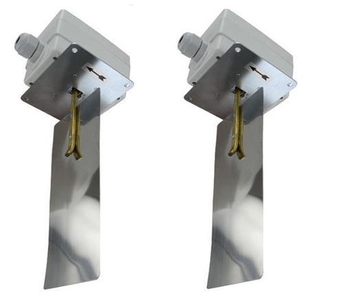
The MODEL AAFS Adjustable Air Flow Switch is capable of detecting a wide range of air velocities with minimal user calibration. Quality features include a stainless steel vane, galvanized steel base, and ABS enclosure.

Features:

  • Adjustable air flow sensitivity from 200 to 1800 FPM:


Installation:

  • Select a location in a horizontal duct at least 10 duct diameters from fans and 7 diameters from elbows, size changes, etc. which can cause turbulence. Also, avoid areas with excess vibration or where the temperature limits might be exceeded. Switch can be mounted in any horizontal duct.
  • Use vane as received for 8 ̋ (203 mm) or larger ducts. Trim for smaller ducts.
  • Cut a mounting hole and slot for the vane and drill four 3/32 ̋ (2.38 mm) screw holes. Insert switch through slot and rotate so arrow on switch enclosure points in direction of air flow. Attach switch to duct with sheet metal screws.
  • To make electrical connections, loosen the retaining screws and remove the conduit enclosure cover. See Figure 2. The SPDT snap switch has screw terminals marked common, normally open and normally closed. A ground screw is also provided. On decreasing flow, the normally open contacts will close and the normally closed contacts will open as the set point is passed.
  • To adjust set point, turn the flat-head screw located under the enclosure cover. Rotate clockwise to increase setting or counter-clockwise to decrease.
  • After all electrical connections and adjustments are complete, replace conduit enclosure cover.


Maintenance/Repair:
The only adjustment is that of the set point. Care should be taken to keep switch dry and free of dust, dirt and oil. No lubrication or routine maintenance is necessary in normal service.

Warranty/Return:
Refer to “Terms and Conditions of Sales” in our catalog and on our website. Contact customer service to receive a Return Goods Authorization number before shipping the product back for repair. Be sure to include a brief description of the problem plus any additional application notes

USB Wireless Receiver

Rs 900 / Piece

Model NumberDWYER USA
%
ConditionNew

USB Wireless Receiver

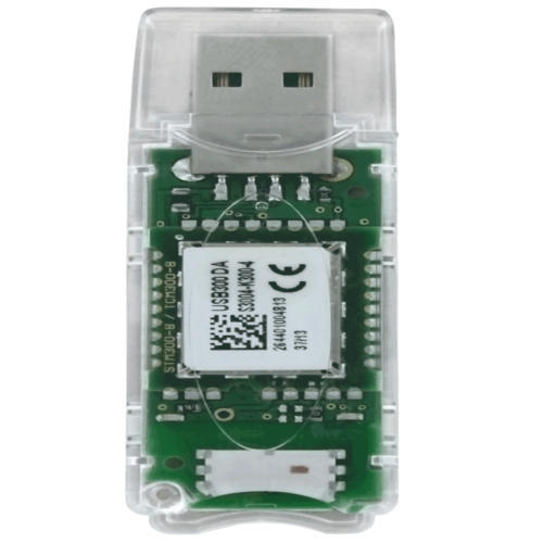
The SERIES USB-300 USB Wireless Receiver is a simple way to allow PC’s to test any EnOcean®-enabled device using wireless technology. This unit is equipped with a TCM 310 transceiver module, which provides bidirectional EnOcean® radio protocol. Radio messages are sent and received through a virtual series interface.

Features:

  • Works with any EnOcean®-enabled device
  • Compact USB design
  • Meets North American


Applications:

  • Building commissioning
  • Troubleshooting systems that incorporate EnOcean® communicating instruments
  • Product installation trials


Other Details:

ModelDescription
USB-300Wireless receiver, 868 MHz (required)
USB-300UWireless receiver, 902 MHz (required)

Temperature Transmitter

Rs 8,500 / Piece

BrandDWYER USA
%
ConditionNew

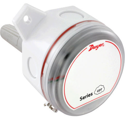
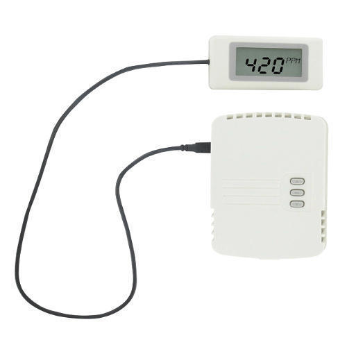
Carbon Dioxide and Temperature Transmitter

The SERIES CDT Carbon Dioxide and Temperature Transmitters accurately monitor the CO2 concentration and temperature in indoor environments to help achieve energy savings. For increased sensor accuracy, a single beam dual wavelength nondispersive infrared (NDIR) sensor is used to automatically correct the measurement in both occupied* and unoccupied buildings against light source aging effects. The single beam dual wavelength sensor technology provides the highest level of accuracy compared to Automatic Baseline Correction methods which can unintentionally shift the calibration based on CO2 levels and barometric pressure conditions. In order to achieve a higher level of accuracy, the Series CDT includes digital barometric pressure adjustment and the ability to field-calibrate the sensor. For applications that require visual indication, the wall mount configurations of the Series CDT can be ordered with an integral LCD display. Push buttons are standard on all configurations of the transmitters for access to the menu structure, but wall mount configurations can be ordered without the buttons. To prevent tampering, the action of the buttons can be locked out using an internal dip switch selection.
For buildings occupied 24 hours per day, it is recommended that calibration be verified every 6 to 12 months depending on application.

Single beam dual-wavelength sensor advantages:

  • Automatically corrects for aging effects in occupied and unoccupied buildings. Perfect for hospitals and manufacturing plants that are occupied 24 hours per day
  • Measures actual unfiltered light intensity directly. Eliminates error from incorrect assumptions of gas concentration in theoretical logic assumption methods


Features:

  • Single beam dual wavelength NDIR sensor eliminates draft due to light source aging
  • Integral passive temperature outputs reduce number of devices mounted in the space
  • Service display tool available for models without an integral LED
  • Optional integral display and relay output


Application:

  • Demand control ventilation in schools, office buildings, hospitals, and other indoor environments
  • LEED ® certification


Technical Specification:

Range:CO2: 0 to 2000 or 0 to 5000 ppm (depending on model); Temperature: 32 to 122°F (0 to 50°C).
Accuracy:CO2: ±40 ppm ±3% of reading; Temperature: ± 1° C @ 25°.
Temperature:±1°C @ 25°C.
Temperature Dependence:±8 ppm/°C at 1100 ppm.
Non-Linearity:16 ppm.
Pressure Dependence:0.13% of reading per mm of Hg.
Response Time:2 min for 99% step change.
Output:Current: 4 to 20 mA (max 500 Ω); Voltage: 0 to 5 VDC or 0 to 10 VDC (min 500 Ω), Relay: SPST NO 2 A @ 30 VDC;

Communicating Carbon Dioxide Detector

Rs 37,500 / Piece

ModelDWYER USA
%
Display TypeDigital

Communicating Carbon Dioxide Detector

The SERIES CDTA Communicating Carbon Dioxide Detector combines the function of three room sensors into a single, compact housing. Parameters include carbon dioxide, humidity, temperature, and temperature set point with override. By having field selectable Mtemperature set point with override. By having field selectable Modbus® and BACnet Communications, only four wires are needed for power and the communication signal. The communicating detectors can be daisy chained together to further reduce installation cost. In order to reduce the set up time, the RS-485 MAC address is set up using on board dip switches. A second set of dip switches are used to select whether output is Modbus® RTU or BACnet MS/TP communication protocols and to limit access to the set up menu. Like our Series CDT Carbon Dioxide Transmitter, the Series CDTA uses a Single Beam Dual Wavelength Non-Dispersive Infrared (NDIR) sensor to measure the carbon dioxide level. This technology can be used in installations that will be occupied 24 hours per day. For improved accuracy, the transmitter can be field calibrated to the environmental conditions of the installation. Also, the barometric pressure can be programmed to correct for altitude. The humidity uses a capacitive polymer sensor and the temperature is measured using a 10KO thermistor sensor. The humidity sensor is field replaceable without the need for additional calibration. Optional local and remote displays are available to display any of the parameters. For applications in which the building occupants aren’t familiar with CO2 concentrations, the LCD can be programmed to display temperature, humidity, or temperature set point instead.
Features:

Field selectable Modbus® and BACnet communications reduces wiringSingle-beam dual-wavelength CO2 sensorReplaceable humidity/temperature sensorPhysical hardware lockoutOptional remote display toolDigital Intelligent Temperature Compensation Algorithm (DITCA™) corrects for errors due to self heating effects of combination wall sensors
Application:

Demand control ventilation in schools, office buildings, hospitals, and other indoor environmentsLEED ® certificationRequestCallback

Carbon Dioxide Temperature Transmitter

Rs 8,500 / Piece

BrandDWYER USA

Carbon Dioxide Temperature Transmitter
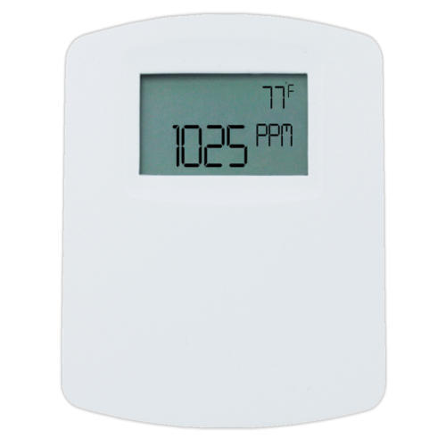
The SERIES CDTR Carbon Dioxide, Relative Humidity and Temperature Transmitters reduce the number of sensors mounted on a wall or in a duct. By combining CO2, RH, and temperature in one device, system integrators are able to reduce installation time while lowering material cost at the same time. Like our popular Series CDT Carbon Dioxide Transmitter, a single beam dual wavelength non-dispersive infrared (NDIR) sensor is used to automatically correct the measurement in both occupied* and unoccupied buildings against light source aging effects. In order to achieve the best possible accuracy, the Series CDTR also includes digital barometric pressure adjustment and the ability to field calibrate the sensor. Universal outputs for both carbon dioxide and relative humidity allow users to select the transmitter output to be 4 to 20 mA, 0 to 5 VDC, or 0 to 10 VDC to work with virtually any building management controller. Additionally, passive thermistor or RTD sensor can be ordered for a temperature output. For applications that require visual indication, the wall mount configurations of the Series CDTR can be ordered with an integral LCD display. The display can be configured to display temperature only, relative humidity only, CO2 only, CO2 and humidity, or CO2 and temperature. Push buttons are standard on all configurations of the transmitters for access to the menu structure. To prevent tampering, the action of the buttons can be locked out using an internal jumper selection.

For buildings occupied 24 hours per day, it is recommended that calibration be verified every 6 to 12 months depending on application.

Features:

  • Digital Intelligence Temperature Compensation Algorithm (DITCA™) eliminates error due to the self heating effects of wall mount combination devices
  • Single beam dual wavelength NDIR CO2 sensor
  • Replaceable humidity/temperature sensors
  • Physical hardware lockout
  • Service display tool available for duct mount and wall mount units without an LCD
  • Relay output option


Application:

  • Demand control ventilation in schools, office buildings, hospitals, and other indoor environments
  • LEED ® certification

Carbon Monoxide Transmitter

Rs 7,000 / Piece

Model NumberDWYER USA
%
Measurement Range0 to 200 ppm.
Accuracy

+/-2% FS at the time of calibration.

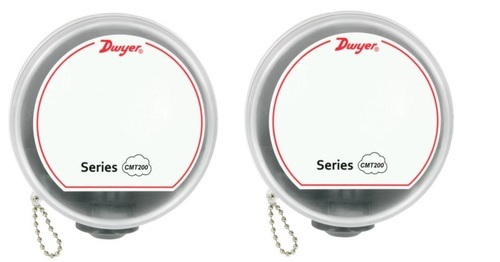
Carbon Monoxide Transmitter

The SERIES CMT200, Carbon Monoxide Transmitter provides a field selectable current or voltage output that is proportional to the gas concentration in underground parking garages, vehicle maintenance facilities, or mechanical rooms. A field replaceable, electrochemical sensor provides accurate readings for up to 4 years with proper calibration. Field calibration can be done by using Model GCK-200CO-2000CO2 calibration gas, Model A-507A calibration adapter, and the on board span and zero potentiometers.

Model Available:

ModelDescription
CMT200Carbon Monoxide Transmitter, 0 to 200 PPM CO, 4 to 20 mA/2 to 10 VDC outputs.
CMT200-RCarbon Monoxide Transmitter, 0 to 200 PPM CO, 4 to 20 mA/2 to 10 VDC outputs, rectangular enclosure


Features:

  • Field selectable current or voltage outputs
  • Replaceable sensor
  • Field calibration kits


Application:

  • Garage ventilation
  • Mechanical room monitoring
  • BAS


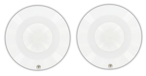
The MODEL OSC-200 Omnidirectional Occupancy Sensor helps to automate building control systems. A spherical Fresnel lens provides a 360° detection zone with the use of infrared technology.

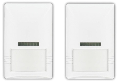
The MODEL OSW-100 Wall Mount Occupancy Sensor is an infrared sensor designed to  help  automate  building  control  systems.  The  Model  OSW-100  has  a  wide  110°  viewing angle to capture movement up to 49.2 ́ (15 m) away

Carbon Monoxide and Nitrogen Dioxide Gas Transmitter

Rs 20,000/ Piece

BrandDWYER USA

Carbon Monoxide and Nitrogen Dioxide Gas Transmitter

Model Available:

ModelDescription
GSTC-CCarbon Monoxide Transmitter with BACnet & Modbus Communication
GSTC-NNitrogen Dioxide Transmitter with BACnet & Modbus Communication
GSTC-C-LCDCarbon Monoxide Transmitter with BACnet & Modbus Communication with Integral LCD Display
GSTC-N-LCDNitrogen Dioxide Transmitter with BACnet & Modbus Communication with Integral LCD Display


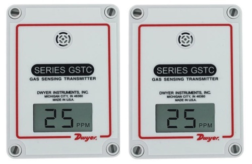
The Series GSTC Carbon Monoxide/nitrogen Dioxide Gas Transmitter monitors the gas concentration in underground parking garages and loading docks. The carbon monoxide transmitter is used to measure the exhaust of gasoline engines, while the nitrogen dioxide transmitter is used for diesel engines. The Series GSTC is compatible with either BACnet or Modbus® communication protocol, allowing the transmitter to be used with almost any building management controller. The GSTC output is communicated over an RS-485 wire via BACnet or Modbus® communication protocol. To maximize the accuracy of the Series GSTC, the sensor can be field-calibrated using the A-449 remote LCD display. When the sensor reaches the end of its life, the display will indicate that the sensor needs to be replaced. BACnet and Modbus® communication protocol recommend limiting the number of nodes in any segment to 32. Therefore, the transceiver may be rated at one unit load. Fractional loads are also acceptable. The Series GSTC accounts as an eighth of a load on the MS/TP network.

Features:

  • Industrial grade replaceable CO or NO2 sensors
  • Field selectable BACnet or Modbus® communication on GSTC models
  • Integral LCD display option
  • Service display tool for set-up and calibration of models without a LCD


Applications:

  • Parking Garages
  • Loading Docks
  • Mechanical Room Monitoring


Technical Specification:

SensorField replaceable electrochemical, 4 years typical lifespan.
Span and Zero AdjustmentVia pushbutton, using optional A-449 display. Zero only via BACnet or MODBUS® communication protocol.
HousingUV resistant glass filled polycarbonate.
Output SignalsBACnet MS/TP, MODBUS® RTU, or MODBUS® ASCII (switch selectable) communication protocol.
lectrical Connection:Removable terminal block, knock outs for conduit fitting.
Calibration:Via pushbuttons using A-449 auxiliary display. Span gas concentration is field selectable.

Fume Hood Monitor

Rs 9,500 / Piece

BrandDWYER USA

Fume Hood Monitor

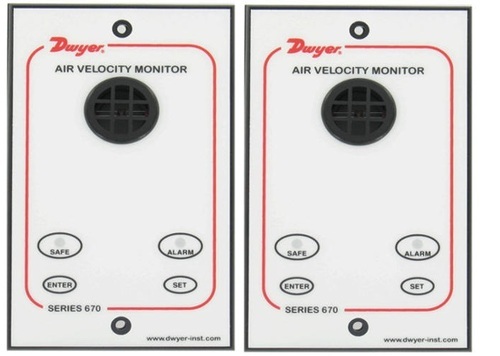
The MODEL 670 Fume Hood Monitor continuously senses air flow through the face of the fume hood, ensuring safe levels of fresh air are exhausting. The 670 provides a highly accurate hot wire sensor to detect very low flows common on fume hoods. The Model 670 comes with everything required to quickly install the unit including a mounting bracket, 24″ of tubing for connecting to the inside of the hood wall and a 120 Volt AC power adapter.

Features:

  • Flexible surface or flush mounting
  • LED safe and alarm status indicators
  • Audible alarm
  • Sash alarm input
  • Night set-back input


Specification:

  • Low Air Velocity Alarm Delay : Fixed 5 secs.
  • Visual LED Display : Red: Alarm; Green: Normal.
  • Horn Silence : Yes, temporary and permanent.
  • Accuracy : Face velocity ±10%.
  • Relay Output Low Air Flow Alarm :5 A @ 250 VAC.
  • Relay Input for Night Setback : 2 wire rated for 24 VDC usage.
  • Sash High Indication : Using a two wire micro switch or 3 wire proximity switch input, rated for 24 VDC usage.
  • Mounting : Semi flush, flush or surface mounted when using included bracket.


Applications:

  • Fume hood ventilation monitoring

Occupancy Sensor

Rs 3,500 / Piece

BrandDWYER USA

Occupancy Sensor

The Model OSC-200 Omnidirectional Occupancy Sensor automatically controls a HVAC ventilation system. A spherical Fresnel lens provides a 360° detection zone with the use of infrared technology. The integrated dual delay processor saves energy by eliminating false activation due to short-term occupancies. The Model OSC-200 is designed to be ceiling mounted, and is pre-wired for ease of installation.

Features:

  • Delay processor suppresses switch activation during momentary occupancy


Applications:

  • Lighting control
  • Building energy conservation


Install Base Unit:

  • Determine the location of the sensor according to the detection pattern shown in Figure 1a.
  • Remove the cover screw to open the sensor housing as shown in Figure 1b.
  • Remove the circuit board by bending the tab outward (Figure 1b.)
  • Screw the base of the sensor housing to the ceiling through the knockout holes


Wiring:
Model OSC-200 is pre-wired for ease of use with 22AWG colored wires. Connect the wires as showin in figure 2

Walk Test:
Before beginning test, make certain that the On and Off Delay jumpers (located on the circuit board) are connected in the “A” positions as shown in Figure 3. If they are not, follow the procedure under the section titled On/Off Delay Settings to rearrange the jumpers to location “A.” Replace the sensor housing and tighten screw.

Storage And Cleaning:
The sensor lens is the most delicate part of the Occupancy Sensor. The lens should be kept clean at all times, care should be taken when cleaning the lens using only a soft cloth or cotton swab with water or medical alcohol. Allow the lens to fully dry before using the sensor. The sensor should be installed or stored in an area of room temperature between -4 and 140ºF (-20 to 60ºC).

Maintenance:
After final installation of the unit, no routine maintenance is required. The Model OSC-200 is not field serviceable and should be returned if repair is needed (field repair should not be attempted and may void warranty). Be sure to include a brief description of the problem plus any relevant application notes. Contact customer service to receive a return goods authorization number before shipping.

Wall Mount Occupancy Sensor

Rs 9,500 / Piece

Range49.2 ft (15 m).
Weight G3.2 oz (90.7 g).
BrandDWYER USA

Wall Mount Occupancy Sensor

The Model OSW-100 Wall Mount Occupancy Sensor is an infrared sensor designed to automatically control an HVAC ventilation system. A unique dual delay processor eliminates false triggers due to short-term occupancies.

Other Details:
Install Base Unit

  • Determine the location of the sensor according to the detection pattern shown in Figure 1.
  • Screw the base of the mounting bracket to the desired position on the wall as shown in Figure 2.
  • Feed the cable through the hole on the back of the bracket.
  • Loosen the screw on the bottom of the sensor and remove the cover.
  • Feed the cable through the center hole on the back of the sensor housing.
  • Attach the sensor to the mounting bracket.


Wiring:

  • Turn the screw for each terminal counterclockwise.
  • Connect the cable to the corresponding terminals as shown in Figure 3


Walk test:
Before beginning test, make certain that the On and Off delay jumpers (located on the circuit board) are connected in the “A” positions as shown in Figure 4. If they are not, follow the procedure under the section titled On/Off Delay Settings torearrange the jumpers to location “A.” Replace the sensor housing and tighten screw.

Storage And Cleaning:
The sensor lens is the most delicate part of the Occupancy Sensor. The lens should be kept clean at all times, care should be taken when cleaning the lens using only a soft cloth or cotton swab with water or medical alcohol. Allow the lens to fully dry before using the sensor.  

Maintenance:
After final installation of the unit, no routine maintenance is required. The Model OSW-100 is not field serviceable and should be returned if repair is needed (field repair should not be attempted and may void warranty). Be sure to include a brief description of the problem plus any relevant application notes. Contact customer service to receive a return goods authorization number before shipping. Request